CPUSim64 Architecture
Overview
CPUSim64 is an emulation of a simple 64-bit microprocessor. All instructions are 64-bit as are all CPU registers. Memory access is done using 64-bit at a time. It is a Load/Store architecture which means that only the load, store, push and pop instructions interact with memory. All other instructions operate on registers.
CPU Model
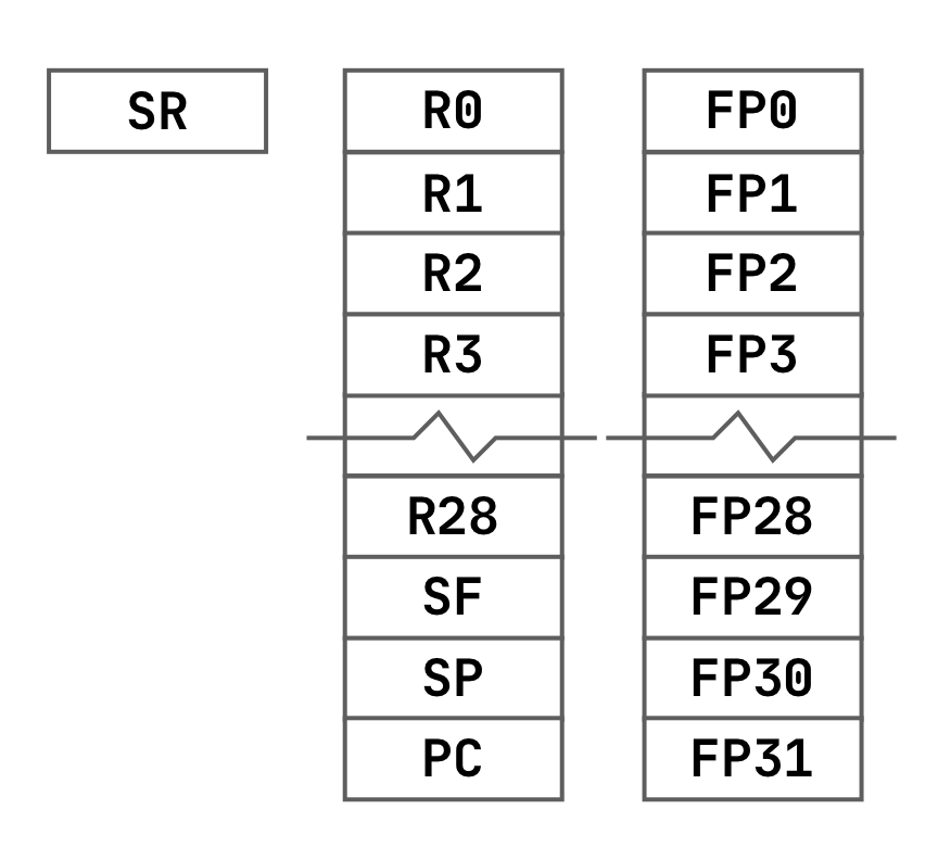
The CPUSim64 CPU has 32 64-bit integer registers that can be used for signed integers or addresses in memory. It also has 32 64-bit floating point registers that can only be used for IEEE 754 floating point values. It also has a special status register used to indicate attributes of the last value loaded or computed.
All of the floating point registers can be used in user programs. None are reserved but the first four F0, F1, F2 and F3 are used as working registers that are not assumed to be preserved by function calls or interrupts. Three of the integer registers are reserved for CPU operation leaving 29 integer registers for use in user programs. The three reserved integer registers are for the Stack Frame (SF), Stack Pointer (SP) and Program Counter (PC):
- SF = R29
- SP = R30
- PC = R31
Like the floating point registers, the first four integer registers R0, R1, R2 and R3 are used as working registers and not assumed to be preserved by function calls or interrupts. The R0 is typically used for function/interrupt return values and the other three are used as inputs to function calls or interrupts.
Program Counter (PC)
The program counter register is used by the CPU to keep track of the next instruction to execute. Each CPU cycle, the instruction in the memory address stored in the PC is loaded, decoded and executed. Then the PC is incremented to point to the next instruction. Control instructions like the JUMP, CALL, RETURN and INTERRUPT instructions can modify the SP to an arbitrary value.
Stack Pointer (SP)
The stack is a region of memory used by the CPU for temporary values. The stack pointer register is used to keep track of where the top of the stack is located in memory. The stack pointer will be modified by the PUSH, POP, CALL and RETURN instructions.
Stack Frame (SF)
When making function calls, arguments and local variables are created on the stack. The stack frame keeps track of where the stack pointer was when the function started so that all local variables can be easily removed from the stack before the function returns. Function call arguments are referenced relative to the stack frame.
Status Register (SR)
The status register is modified when ever we use a test/compare instruction, move/load instruction, an arithmetic instruction or a logical instruction based on the result if the instruction. Individual bits set in the status register include: overflow, sign, zero and parity. The overflow bit is set if the result overflows integer or floating point arithmetic. The sign bit is set for negative results. The zero bit is set if the result is zero. Finally the parity bit is set if the parity is odd and not set if it is even. Parity is a count of the 1 bits found in a number. You can not access the status register directly only indirectly indirectly using conditional instructions like JUMP, CALL, INT or the conditional MOVE.
Memory Model
There are three regions of memory used by programs run by the CPU. They are Code/Data, Heap and Stack.
Code/Data Region
Your assembled machine code for your user program is loaded into memory for the CPU to execute. This code/data region typically starts at address 0x1 and ends at the beginning of the heap. Not only are machine instructions stored in the code region, but also any floating point or string literals defined in your program. It is condsidered bad practice to modifiy code in the code region which is why it is marked as read-only. The data portion of the code/data region is where read-write static variables can be created using the #global preprocessor directive.
Heap
The heap is the region of memory where blocks of memory can be dynamically allocated for use by your program. Typically arrays or other complex data structures would be allocated in the heap. The heap begins at the end of the code/data region and ends at the maximum size allocated for the stack.
Stack
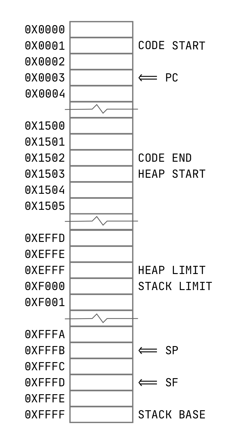
The stack is a region of memory used by the CPU and user programs for temporary storage. It is a last-in/first-out (LIFO) data structure. The stack resembles a stack of plates where the last plate put on the stack is the first one taken off. The stack starts at the top of available memory 0xFFFFFFFFFFFF and grows down toward the heap. It is considered an error if you allow the stack to grow so much that it overwrites some of the heap. This is known as a stack/heap collision.
The SP register always points to the next free location on the stack. The SP should always point to a memory location between the stack base at the top of memory and the stack limit. The SF points to the location of the SP when the latest function call was invoked. It points to the beginning of function local variables and should always be between the stack base and the SP.
The diagram below illustrates an example of the layout of memory assuming that 0x10000 (or 65,536) 64-bit words are available to your application. Unlike many CPUs that address memory byte-by-byte, CPUSim64 can only access memory as 64-bit words. This simplifies memory addressing removing the limits other processors have that they can only load on word boundaries every eight bytes, i.e. eight addresses. In CPUSim64 there is no need to multiply all our address locations by eight to get a valid address.